Transmission Site Transmitter Info
Antenna Type
All Antennas have radiation patterns. While these patterns will vary based on a number of variables, the common items are vertical and horizontal beamwidths, and electrical down tilt. TowerCoverage.com has been designed to utilize these antenna patterns.
TowerCoverage.com ONLY uses patterns supplied to us by the antenna’s manufacturer. We have also provided several generic antenna patterns. Using the exact antenna pattern for your antenna will help improve the accuracy of your coverage maps, but some users find the generic patterns are good enough for their intended usage.
The general rule of thumb is to choose the specific antenna you are using. If your specific antenna is not listed, you can also upload your own. See the Upload Antenna Pattern section for more details.
Antenna Azimuth
The Antenna Azimuth is the direction that the antenna is pointing (only for directional antennas, not omni antennas). In most cases you will be using a spectral antenna.
Beamwidth Filter
The Beam width Filter field is designed to give the creator of the coverage the ability to set the width of the antenna they choose to use. This allows you to set the coverage to a specific degree and take into account the side lobes of the antenna pattern.By default, when you select the antenna you would like to use, the Beam width will auto fill using the antenna files. If you would like to modify it afterwards you can do so. Each time you change the antenna, it will change the field as well.
When you perform a Path Analysis or a customer fills out your EUS Form, the link results for any given coverage will not display if the location is outside the beamwidth. If you would like to be able to utilize side lobes of an antenna you will need to add to the beamwidth of the coverage.
Antenna Tilt
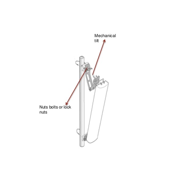
The Antenna Tilt is for adding or removing mechanical antenna tilt. Some antennas have electrical tilt which should be included in the antenna pattern, so you will not need to enter anything other than zero here. However, if your antenna has a physical tilt to it, you need to enter the correction here.

Antenna Gain
Client Antenna Gain is the normal dBi of the antennas you use. If you are looking to create a map with the maximum coverage area you will need to enter your largest receiving radio’s values here. If you want to standardize based on the normal radio you would use, not the largest you can use, your coverage will be smaller. This is a technical decision on what you want your coverage map to show. Again, if you want the maximum coverage, then you would enter the largest value that you would actually use in the antenna gain field. For WISP operations, we would recommend to put the largest antenna that you allow your installers to install with to provide you the maximum coverage area.Frequency
Exact Center Frequency
Exact Center Freq is an optional field for the frequency usage plot on Multi Maps. This is the exact frequency that you currently have this transmitter operating on.For Example: You have selected WIFI 2.4 GHz for your frequency band and this antenna is operating at channel 2417. You may choose to enter 2417 in the Exact Center Freq field. Again, this is not a required field for TowerCoverage.com. Entering the exact frequency of this coverage can help you see possible interference on your own network.