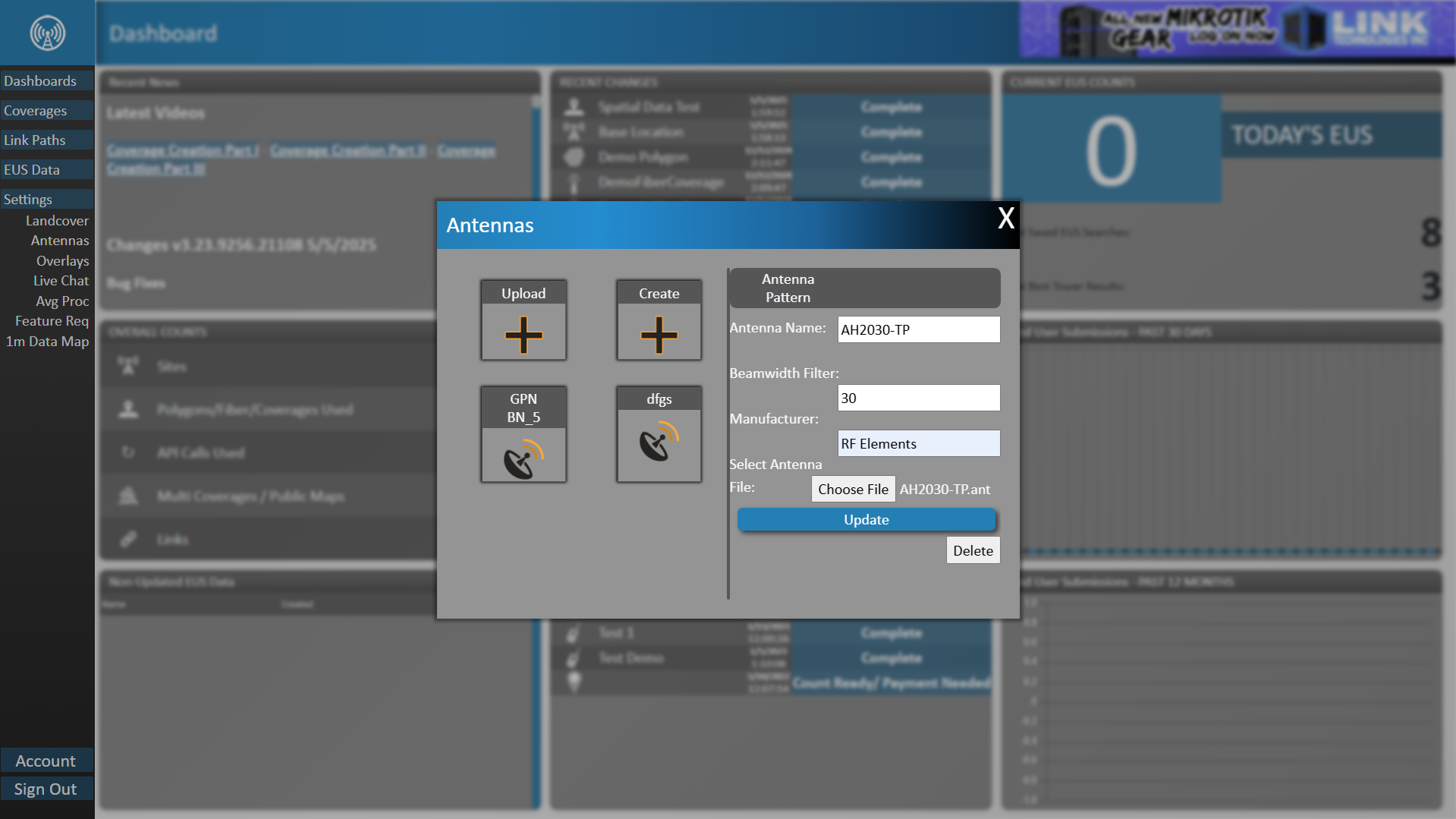
Upload / Create Antenna Pattern
Add New Antenna Pattern
In TowerCoverage.com, we have a list of several pre-loaded antenna pattern files you can select from. All pattern files that are in the drop down list have been provided by the manufacturer of the given antenna to maintain accuracy and have not been modified by our developers. If you do not see the pattern you wish to use in the list you have the ability to add your own antenna pattern files to match your equipment. We suggest that you obtain these directly from the manufacturer to ensure that you do not get inaccuracies in you coverages.
This feature can be found by clicking on Antenna Patterns, under the settings section of the left side navigation bar.
When the files are uploaded, the system will verify that it is a valid file. The file used should be a Radio Mobile Compatible .ant file. We have also added a downloadable file that will allow you to ensure the files are in the correct format or forward to the manufacturer to create the file for you.
Antenna pattern files can be deleted if you no longer want them in your account, but only an account admin has the permission level required to do so.
- The file should contain 720 rows of data.
- Line 1 and line 451 should match. This is the gain at azimuth degree 0 and elevation angle of 0.
- Line 181 and Line 631 should match. This is the gain at azimuth degree of 180 and the elevation angle of -180.
- Beamwidth Filter must be valid. (numerical value only). See the beamwidth section for more information.
Update Pending
Previously users had to download a excel document and insert values for the gain values in individual cells. Once they had done so, they then had to copy the corresponding columns to their clipboard, paste those values into a notepad program and save the document as a .ant file. Next, they would go to TowerCoverage.com and input the settings, then upload the file they created to save an antenna for use in creating Coverages/Radio Systems. This will no longer be necessary. Users can use the Antenna Pattern File Creator without having to go in and out of TowerCoverage for creating, saving, and uploading files.(The Excel document is still available for download via the new interface for those that prefer to use that method)
In the Pattern Creation Interface, users can select the step value that they want to input for Azimuth and Elevation
Users can also set wether they wish to normalize the peak reading to 0 via a checkbox. When the checkbox is active TowerCoverage will shift the whole pattern up or down so that the highest value becomes 0 dB, and everything else is shown relative to that peak.
Think of this like setting the tallest bar in a bar chart to 0, and measuring all other bars by how far below the tallest bar they are. It doesn’t change the shape of your pattern, only the reference point. You'd just be setting “The loudest point = 0”.
Why would you do this? Because it makes plots and comparisons easier (since 0 dB is the outer ring / peak). This lets you compare different antennas without worrying about their absolute max gain.
If you leave it unchecked, The values stay as-is (absolute). Your peak might be +12 dB, and the plot’s numbers won’t be centered around 0. Enter the gain values by entering each one and separating it by a comma. The Azimuth Field contains some place holder text by default, meant to indicate how the values should be formatted when you enter them.
Once you click "Create" it will check that you have entered values accordingly and validate the file. At that point it will either give you an error notice, or it will display the result in the right side window of what the expected outcome is. You can change as many values as you like and update the pattern simply by clicking the create button again as many times as you wish.
Click Save once you are satisfied with the pattern and a Modal will appear so that you can enter the Name of the Antenna, The Manufacturer and the BeamWidth. Keep in mind that the BeamWidth does NOT change the outcome of the antenna nor does it affect the propagation of a Coverage when the antenna is used. It simply is a restrictor value so that EUS (End User Submission) Data is not checked against the coverage if the user location is outside the beam width of the coverage.
It is also worth noting that this is not a finite setting. The BeamWidth is used when creating a Coverage so that when you select the given antenna, it auto populates the BeamWidth Filter setting in the Coverage creation process. It can be modified on a case by case basis as the antenna is used.