Fiber Maps
Document fiber routes and service areas with the fiber map editor.
Before you Start
The Fiber Map Feature uses Mapbox and needs WebGL.
If the map is blank, try another browser or enable WebGL.
If you see a message about a missing Mapbox token, an administrator must configure the site.
Importing a Coverage
- Import a fiber layout by clicking the "Import (KMZ/KML/ZIP - KML or SHP)" button on the main page of the fiber creation interface.
- The Import wizard will read the file and then walk you through it, letting you assign values in bulk to fit the TC schema.
- It will automatically add any placeholders (markers) you have in the file as objects on the map.
- Any placeholders you have tagged to the end of a line will be auto set as termination points.
- It will also scan for any polygons you may have included in the upload and will (on the fly) create Polygon maps for those (if you elect to utilize that option).
- All fibers can be assigned the different types of fiber, and the tubes and strands are automatically color coded to industry standards for ease of use.
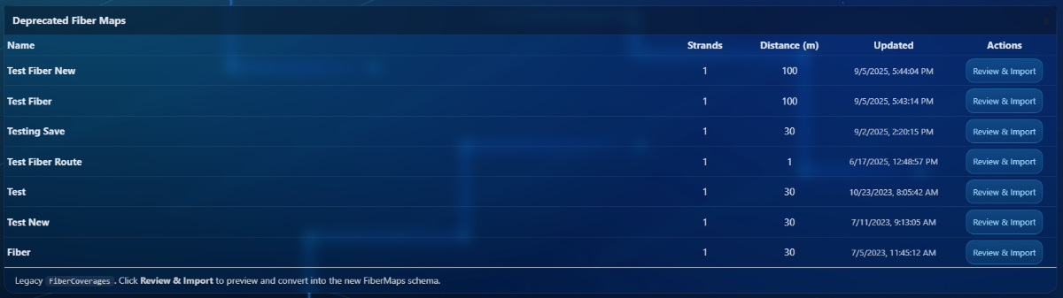
- You'll find previously created legacy fiber coverages at the top of your fiber coverage list.
Creating a New Fiber / Cable Coverage
Mapping out a Fiber / Cable route differs from standard coverage creation in that instead of generating an RF propagation based on a given set of parameters, you'll create your route by adding pins along the path. The process involves running a route or routes through the areas you can cover and setting the serviceable distance of the coverage. The path you create will form the necessary polygons for your BDC availability data, along with a call out in your Path Analysis as well as show in your EUS Data if the location falls within its coverage area.
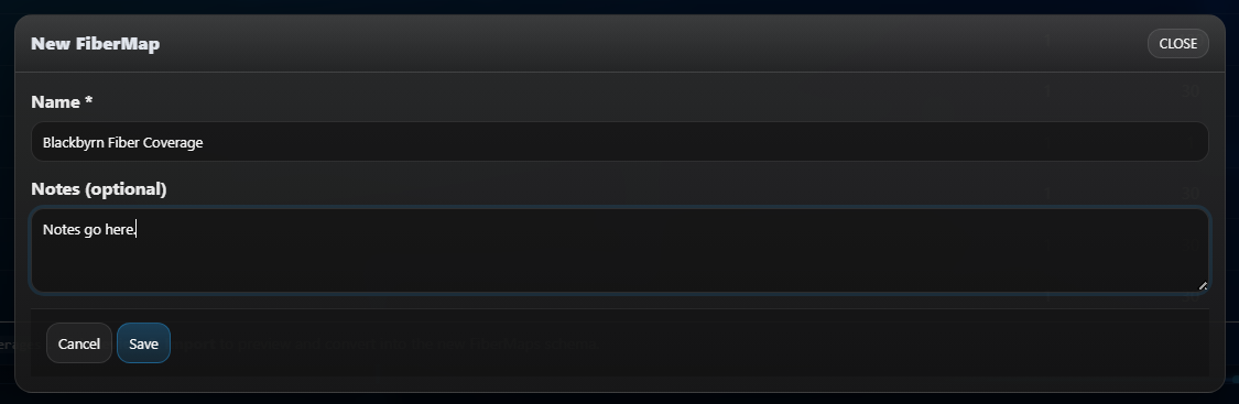
To create a new Fiber Map you'll need to click on the "+ New FiberMap" button.

Next, you'll give it a name, and you can include some notes if you have any you'd like to provide.
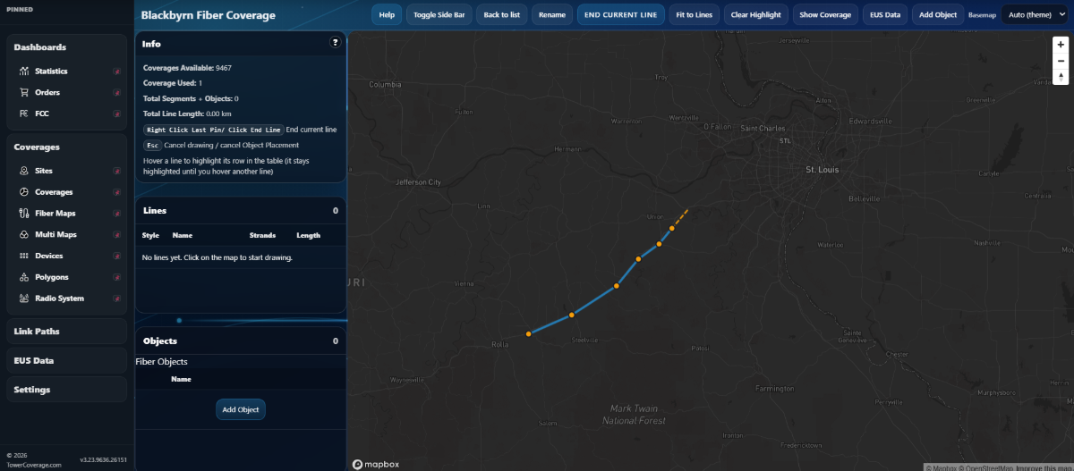
Click the map to begin creating your path. Add pins along the path until you reach your desired end point. Right click a pin to terminate the line.
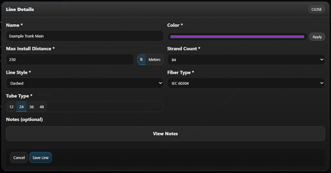
Once the line is terminated it will bring up a settings screen. Fill in the details and click "Save Line" to finalize your path.
Click anywhere on the map to add a new path. If you'd like to anchor a path to a previous line, you'll need to create a splice point. See "Procedure to Place an Object" below for more details.
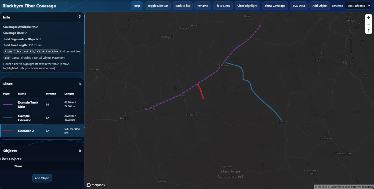
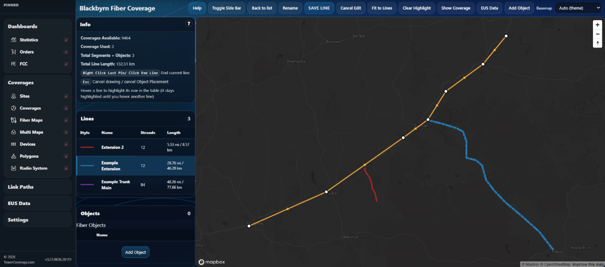
Click on an existing line in the lines list to edit the path's values. Right Click on any pin to delete the pin. Click and drag a pin to move its location. Click the save line button to commit your changes. You can cancel the edit at any time prior to committing your changes by clicking the cancel button.
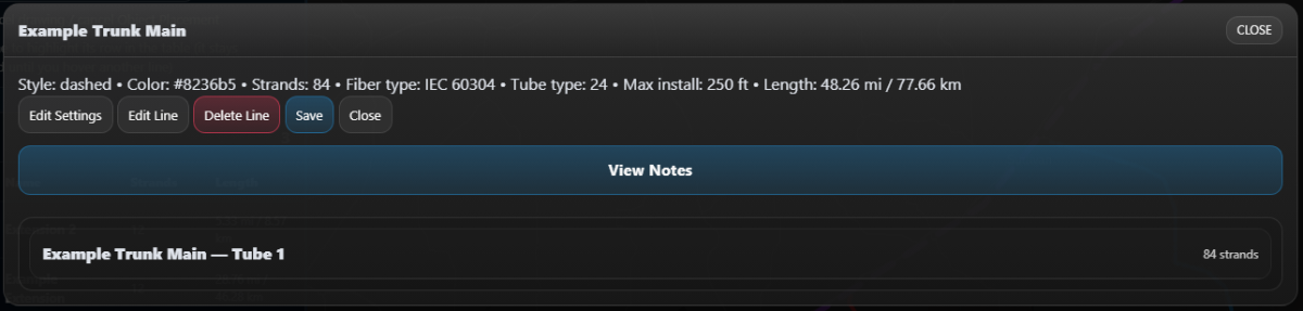
Fields (New Fiber Coverage)
Name
This name should be unique so that after creating the Fiber / Cable route, it can be identified if it is returned in a Path Analysis or End User Submission.
Notes
The Notes field is meant to contain data for your tracking and record keeping purposes.
Max Install Distance
The Max Install Distance field is used to create the polygon after updating the Fiber Coverage. This value is also used if your Fiber Coverage is included in a Multi Map; in the Path Analysis feature as well as the End User Submission results. If the potential customer is located within the given Distance allowed, the name of the Fiber Coverage it is within will be returned in the results along with the 6 best possible links.
Color
You can set the Polygon color for a single Fiber Coverage, but the colors will be returned to Blue/Orange Polygons when added to Multi Maps.
Strand Count / Line Style / Fiber Type / Tube Type
These values are used for your record purposes in your TowerCoverage.com account.
- In regards to Strand Count, TowerCoverage provides a drop down list for an array of options. The maximum Strand Count available is 432.
- You can choose a Line Style (Solid, Dashed, or Dashed Plus Dot)
- You can select your Fiber Type (TIA-598-C, and IEC 60304)
- You can select your Tube Type (12, 24, 36, 48)
Objects
Terminations, Splice Points, Cubes, or other data can be added to your Fiber Network in the form of Objects.
Top Navigation Bar (Buttons)
Help
Click the Help button to access the Fiber Map Builder Help Documentation.
This guide explains the Fiber Map Builder (FiberMaps Edit page): drawing routes, editing lines, strand notes, objects, coverage, and shortcuts.
Toggle Side Bar
You can toggle the side bar to expand your map view.
Back to List
The Back to List Button navigates back to the Fiber Coverages main menu, where you'll find your list of existing Fiber Coverages, and the + New FiberMap >> Import (KMZ/KML/ZIP or SHP) buttons to begin a new build.
Rename
The Rename Button allows you to Rename the existing Fiber Map and Edit the notes associated with that map.
Fit to Lines
Adjusts the view of the map from it's current state to fill the viewing area. It may increase in size or shrink to fit depending on it's current state.
Usage Report
Shows a breakdown of the estimated fiber needed to install what's represented on a given map.
Signal Checker
The fiber signal checker takes the paths set by the wire map and calculates the loss per distance between a pair of objects.
To begin this process you'll need to select a pair of objects.
The Fiber Signal Checker will then evaluate the strand mapping to find the appropriate route between the points.
The signal is then determined by calculating the estimated loss per foot to determine the overall loss from one object to another.
Estimated loss per foot is based on the fiber type selected and loss declared at the splice points
Show Coverage
Displays the coverage using the distance value to represent the complete coverage area. (This is how it would be represented on a MultiMap.)
POP Est.
An estimate of the population covered in the current fiber map.
Overlays
List of KML Overlays that have been uploaded under the Settings >> Overlays section of TowerCoverage.com. Check an item from the list to display it overlayed on your Fiber Map.
EUS Data
Select an Option to display End User Submissions Overlayed as Pins across your Coverage Area to check where they are in your current setup.
Packages
Assign a Service Package to your Fiber Network and display it to potential customers when they fill out your Data Collection Form.
Add Object (New)
Type
- Termination is the end of a line.
- Point is where cables meet.
- Cube and Other are general pins.
Placement
- On Line sticks the object to a fiber line.
- Free-standing puts it anywhere on the map.
Procedure to Place an Object
- Click "Add Object" from the options available at the top of the screen.
- Select an Icon.
- Give the object a name.
- Add some notes.
- Save your changes.
- Drop the object in the same manner you would use to drop a pin on your map.
Wire Map (From the Main Menu)
Opens a picture that shows every strand splice on the whole fiber map.
- Drag the picture to move around.
- Scroll to zoom in and out.
- Show all strands puts each object in its own area.
- The cables that meet there sit beside it.
- A dashed line shows where a cable also continues to another object.
- Zoom in, then drag a colored dot, or a Tube pill, from one cable onto another to connect them.
- Click a colored connection to edit the notes or remove it.
- If one side is a device, you see the fiber note and an address for that strand.
- Devices sit beside the cables.
- One that has strands plugged in stays next to those cables.
- One that is only linked to another device sits farther out.
- Hover an object on the map and click a device picture to open that device.
- Show unusable strands marks strands that cannot be used.
- Unusable strands list opens that list.
Conflict Checker
Checks that the connected strands match up the full distance and that strand counts cannot be skewed in the wrong direction.
Example:
If your main line is 24 strand fiber and you created a line spliced off it and you set the spliced line as 36, it will let you know that you have odd scenario.
Auto (Theme)
You can choose from Light, Streets, Outdoors, Satellite or Dark Mode. Satellite view is only available to Fiber Maps with less than or equal to 100 lines. The imagery is too heavy to draw with larger amounts of Map Data.
Side Bar
Info Box
The info box shows how much of your fiber allowance the map is using.
- Coverages Available is how much room you have left.
- Coverage Used is how much this map already uses.
- Total Segments + Objects counts the pieces on the map.
- Total Line Length is how long all of the lines are together.
Lines Box
Contains a list of every fiber line on the map.
- The colored mark shows the line style. The number is how many strands are in the cable.
- Click a row to open that line.
- Hover a line on the map to highlight its row here.
Objects Box
Contains a list of objects that have been placed in the current network.
- Click a row, or the pin on the map, to open that object.
- Use the Add Object above the map to place a new one.
Edit Line Menu
Edit Settings
Allows you to edit the settings for the line without altering pin any placements.
Edit Line
Allows you to alter or add pins to an existing path.
Swap Ends
Swaps the Start and End points marked for the line.
Delete Line
Deletes the line. (This operation cannot be undone, please proceed with caution.)
Save
Saves your changes.
Close
Closes the editor.
Tube
Displays a color Coded list of each individual strand based on selected strand count. Contains a "Notes" input field for each individual strand.
Object Details Menu
Type and Placement Menus remain the same as they do during new object creation. You can alter the Type and Placement of an object here.
- Click the Relocate on map button to change an object's position. Click Confirm or Cancel to Save or Abandon your changes.
You can change the name or edit the notes associated with the object under their respective fields.
Click the Add Device button to assign a device to an object. Multiple Devices can be added to the same object.
- Device Name
- Type
- Manhole
- Access Point
- Hut
- Notes
- Switch
- Box
- Group
- Notes
Provide a unique name for the Device. (Must be alphanumeric and can contain dashes or underscore only.)
There are several device types available to add to an object.
Group is optional but beneficial when it comes to organization.
The Notes field is meant to contain data for your tracking and record keeping purposes.
The View Details Button takes you to a separate Object Details Page.
This page shows one object and the fiber lines attached to it.
- The top card is the object itself.
- The wire map shows how strands are spliced here.
- The attached lines list is where you open each cable, open a tube, and connect strands.
- Back to map returns to the fiber map.
The Wire Diagram from the Object Details Menu shows how the cables, strands, and devices meet at the specified object.
- Drag to move the picture. Scroll, or use + and −, to zoom.
- Drag a strand dot, or a Tube handle, from one cable onto another cable or onto a device.
- Click a connection to edit the notes or remove it.
- If one side is a device, you see the fiber note and the address on that strand.
- Click Tube on a device connection to see the strands in that tube.
- A device that has strands plugged in sits next to those cables.
- A device that is only linked to another device sits farther out, so new plugs do not pile on top of the first device.